
-
TERMINALS
- TERMINALS
-
WIRELESS MODULES
- WIRELESS MODULES
-
DEVELOPMENT BOARDS & KITS
- DEVELOPMENT BOARDS & KITS
-
RF and Wireless
- RF and Wireless
-
SINGLE BOARD COMPUTER
- SINGLE BOARD COMPUTER
-
BREAKOUT BOARDS
- BREAKOUT BOARDS
-
LED
- LED
-
LCD & DISPLAYS
- LCD & DISPLAYS
-
TEST AND MEASUREMENT
- TEST AND MEASUREMENT
-
DEVELOPMENT BOARDS AND IC's
- DEVELOPMENT BOARDS AND IC's
-
CABLES/WIRES/FANS
- CABLES/WIRES/FANS
-
EMBEDDED COMPUTERS
- EMBEDDED COMPUTERS
-
INDUSTRAL AUTOMATION AND CONTROL
- INDUSTRAL AUTOMATION AND CONTROL
-
COMPUTER EQUIPMENT
- COMPUTER EQUIPMENT
-
CONNECTORS & INTERCONNECTS
- CONNECTORS & INTERCONNECTS
-
MOTORS/DRIVERS/ACTUATORS/MODULES
- MOTORS/DRIVERS/ACTUATORS/MODULES
-
MAKER/DIY EDUCATIONAL
- MAKER/DIY EDUCATIONAL
-
BASIC COMPONENTS
- BASIC COMPONENTS
-
TOOLS & ACCESSORIES
- TOOLS & ACCESSORIES
-
FPGA HARDWARE
- FPGA HARDWARE
-
ARTILA
- ARTILA
-
POWER SUPPLIES
- POWER SUPPLIES
-
ROBOTICS & AUTOMATION
- ROBOTICS & AUTOMATION
-
TRANSDUCERS
- TRANSDUCERS
-
MEMORY CARDS & MODULES
- MEMORY CARDS & MODULES
-
SOFTWARE
- SOFTWARE

ESP8266 WiFi 5V 1 Channel Relay Module equip with ESP8266 WiFi module and micro-controllers, through the mobile phone APP to the module to send serial instructions to achieve in the LAN within the relay for wireless control. This onboard 5V, 10A / 250V AC 10A / 30V DC relay, can be continuous pull 10 million times, with diarrhea flow protection and short response time.
How to use :
- Onboard ESP8266 WIFI module has three operating modes: STA (client), AP (hot), STA + AP (client + hot), according to the work of the module to select the corresponding WIFI module mode of operation The
- The module needs to use the serial debugging software on the computer and USB to TTL module to send AT commands to configure the WIFI module, USB to TTL module RX, TX, GND pin, then the module on the TX, RX, GND pin, IN +, IN – 5V power supply.
Note: This product is available in 2 relay module types: JQC3F-5VDC-C and SRD-05VDC-SL-C. It will be shipped randomly.
General Info :
- Onboard ESP8266 WIFI module, AP mode can be connected at the same time 5 client
- The module has two ways to work:
(i) mobile phone directly mounted on the WIFI module;
(ii) mobile phone and WIFI module also carried on the router.
Transmission distance:
- Open environment, the mobile phone mounted on the WIFI module when the maximum transmission distance of 400m.
- When the WiFI module and mobile phone at the same time carried on the router when the transmission distance according to the router’s signal weakly;
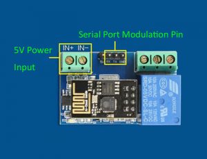
Board function description :
IN +, IN-: 5V power input;
TX, RX, GND: Serial debug pin;
Onboard the ESP8266 WIFI module has three work modes: STA (client), AP (hot), the STA + Ap( hot +client), according to the workings of a module to the corresponding choice of WIFI module working mode. Module need before use serial debugging software and USB to TTL module send serial command was carried out on the WIFI module configuration (don’t power outages after configuration is complete, as some of the parameters of WIFI module cannot be saved when the power is cut off), mobile phone and WIFI module after establishing a network connection can use the phone APP control relay.
Control Commands :
When cell phone equipped with WiFi module sends commands in the following order:
(The default baud rate 115200)
- AT+CWMODE=2, namely AP mode is selected.
- AT+RST, reset.
- AT+CIPMUX=1, open multiple connections.
- AT+CIPSERVER=1,8080, configure the TCP server, set the port.
- AT+CIOBAUD=9600 set the baud rate to 9600. (working in relays to control the baud rate 9600).
- AT+CIFSR to view the AP mode IP address, such as the APIP, “192.168.4.1”.
- Cell phone WIFI signal connection name starts with AI-THINKER or ESP8266.
- In the “TCP connection” address and port into the APP, such as 192.168.4.1 and 8080.
- Click on the grey box relays can be controlled.
Features :
- Onboard Module: ESP8266 wifi module; in AP mode it can connect with 5 Clients at the same time
- Operating Way: cellphone carried on wifi module; cellphone and wifi module carried on the same router, and use the APP to control relay
- Diode effusion protection;
- Short response time
Package Includes :
1 x ESP8266 WiFi 5V 1-Channel Relay Module
Useful Links:
IOT Application
- Home
- MARKETPLACE
- ESP8266 WiFi 5V 1 Channel Relay Module

ESP8266 WiFi 5V 1 Channel Relay Module
SIZE GUIDE
- Shipping in 10-12 Working Days
Description of product
ESP8266 WiFi 5V 1 Channel Relay Module equip with ESP8266 WiFi module and micro-controllers, through the mobile phone APP to the module to send serial instructions to achieve in the LAN within the relay for wireless control. This onboard 5V, 10A / 250V AC 10A / 30V DC relay, can be continuous pull 10 million times, with diarrhea flow protection and short response time.
How to use :
- Onboard ESP8266 WIFI module has three operating modes: STA (client), AP (hot), STA + AP (client + hot), according to the work of the module to select the corresponding WIFI module mode of operation The
- The module needs to use the serial debugging software on the computer and USB to TTL module to send AT commands to configure the WIFI module, USB to TTL module RX, TX, GND pin, then the module on the TX, RX, GND pin, IN +, IN – 5V power supply.
Note: This product is available in 2 relay module types: JQC3F-5VDC-C and SRD-05VDC-SL-C. It will be shipped randomly.
General Info :
- Onboard ESP8266 WIFI module, AP mode can be connected at the same time 5 client
- The module has two ways to work:
(i) mobile phone directly mounted on the WIFI module;
(ii) mobile phone and WIFI module also carried on the router.
Transmission distance:
- Open environment, the mobile phone mounted on the WIFI module when the maximum transmission distance of 400m.
- When the WiFI module and mobile phone at the same time carried on the router when the transmission distance according to the router’s signal weakly;
Board function description :
IN +, IN-: 5V power input;
TX, RX, GND: Serial debug pin;
Onboard the ESP8266 WIFI module has three work modes: STA (client), AP (hot), the STA + Ap( hot +client), according to the workings of a module to the corresponding choice of WIFI module working mode. Module need before use serial debugging software and USB to TTL module send serial command was carried out on the WIFI module configuration (don’t power outages after configuration is complete, as some of the parameters of WIFI module cannot be saved when the power is cut off), mobile phone and WIFI module after establishing a network connection can use the phone APP control relay.
Control Commands :
When cell phone equipped with WiFi module sends commands in the following order:
(The default baud rate 115200)
- AT+CWMODE=2, namely AP mode is selected.
- AT+RST, reset.
- AT+CIPMUX=1, open multiple connections.
- AT+CIPSERVER=1,8080, configure the TCP server, set the port.
- AT+CIOBAUD=9600 set the baud rate to 9600. (working in relays to control the baud rate 9600).
- AT+CIFSR to view the AP mode IP address, such as the APIP, “192.168.4.1”.
- Cell phone WIFI signal connection name starts with AI-THINKER or ESP8266.
- In the “TCP connection” address and port into the APP, such as 192.168.4.1 and 8080.
- Click on the grey box relays can be controlled.
Features :
- Onboard Module: ESP8266 wifi module; in AP mode it can connect with 5 Clients at the same time
- Operating Way: cellphone carried on wifi module; cellphone and wifi module carried on the same router, and use the APP to control relay
- Diode effusion protection;
- Short response time
Package Includes :
1 x ESP8266 WiFi 5V 1-Channel Relay Module
Useful Links:
IOT Application
Related products


")
")
")


")
NEWSLETTER
Subscribe to get Email Updates!
Thanks for subscribe.
Your response has been recorded.
INFORMATION
ACCOUNT
ADDRESS
Tenet Technetronics# 2514/U, 7th 'A' Main Road, Opp. to BBMP Swimming Pool, Hampinagar, Vijayanagar 2nd Stage.
Bangalore
Karnataka - 560104
IN
Tenet Technetronics focuses on “Simplifying Technology for Life” and has been striving to deliver the same from the day of its inception since 2007. Founded by young set of graduates with guidance from ardent professionals and academicians the company focuses on delivering high quality products to its customers at the right cost considering the support and lifelong engagement with customers. “We don’t believe in a sell and forget model “and concentrate and building relationships with customers that accelerates, enhances as well as provides excellence in their next exciting project.