
-
TRANSDUCERS
- TRANSDUCERS
-
BASIC COMPONENTS DK
- BASIC COMPONENTS DK
-
MARKETPLACE
- MARKETPLACE
-
DEVELOPMENT BOARDS & KITS
- DEVELOPMENT BOARDS & KITS
-
CABLE ASSEMBLIES
- CABLE ASSEMBLIES
-
RF AND WIRELESS
- RF AND WIRELESS
-
BOXES ENCLOSURES RACKS
- BOXES ENCLOSURES RACKS
-
AUDIO PRODUCTS
- AUDIO PRODUCTS
-
ARTILA
- ARTILA
-
FANS-BLOWERS-THERMAL MANAGEMENT
- FANS-BLOWERS-THERMAL MANAGEMENT
-
WIRELESS MODULES
- WIRELESS MODULES
-
TERMINALS
- TERMINALS
-
Cables/Wires
- Cables/Wires
-
SINGLE BOARD COMPUTER
- SINGLE BOARD COMPUTER
-
BREAKOUT BOARDS
- BREAKOUT BOARDS
-
LED
- LED
-
TEST AND MEASUREMENT
- TEST AND MEASUREMENT
-
POTENTIONMETERS AND VARIABLE RESISTORS
- POTENTIONMETERS AND VARIABLE RESISTORS
-
DEVELOPMENT BOARDS AND IC's
- DEVELOPMENT BOARDS AND IC's
-
EMBEDDED COMPUTERS
- EMBEDDED COMPUTERS
-
OPTOELECTRONICS
- OPTOELECTRONICS
-
INDUSTRAL AUTOMATION AND CONTROL
- INDUSTRAL AUTOMATION AND CONTROL
-
COMPUTER EQUIPMENT
- COMPUTER EQUIPMENT
-
CONNECTORS & INTERCONNECTS
- CONNECTORS & INTERCONNECTS
-
MAKER/DIY EDUCATIONAL
- MAKER/DIY EDUCATIONAL
-
TOOLS
- TOOLS
-
MOTORS/ACTUATORS/SOLEENOIDS/DRIVERS
- MOTORS/ACTUATORS/SOLEENOIDS/DRIVERS
-
FPGA HARDWARE
- FPGA HARDWARE
-
POWER SUPPLIES
- POWER SUPPLIES
-
ROBOTICS & AUTOMATION
- ROBOTICS & AUTOMATION

Description
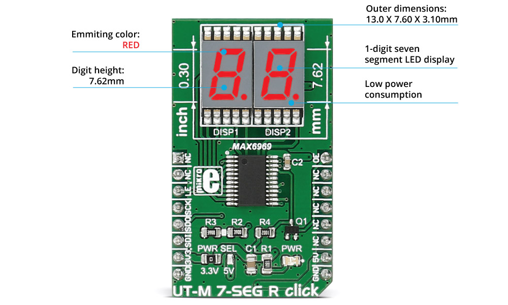
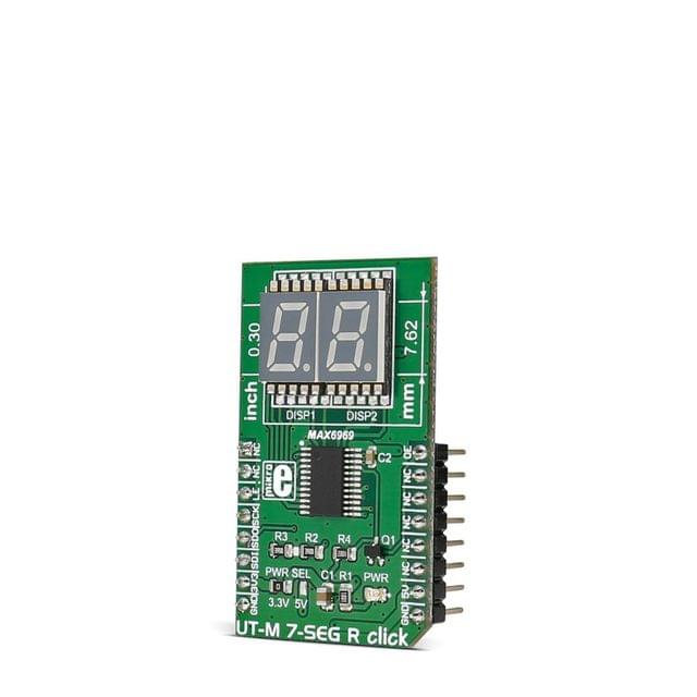
UT-M 7-SEG R click carries two SMD ultra thin LED 7-SEG displays and the MAX6969 constant-current LED driver from Maxim Integrated. The click is designed to run on either 3.3V or 5V power supply. It communicates with the target microcontroller over SPI interface.
Display features
How the click works
The 7 segment displays are interfaced to the MCU over the MAX6969 16-port, constant-current LED driver IC.
It uses the common 4-wire serial bus for communication with the MCU itself (LE, SCK, SDO, SDI on mikroBUS™ pin socket).
There is an additional OE (output enable) pin which is used to control the output driver state (enabled/disabled). Since it is the PWM output pin on the mikroBUS™ by default, the LED segments light intensity could be controlled by software too.
MAX6969 driver features
The MAX6969 uses the industry-standard, shift-register-plus-latch-type serial interface.
The driver accepts data shifted into a 16-bit shift register using data input DIN and clock input CLK. Input data appears at the DOUT output 16 clock cycles later to allow cascading of multiple MAX6969s. So, the IC allows you to connect multiple click boards™ - for applications that require more than two seven segment displays, such as digital clocks, temperature sensors, etc.
Specifications
| Type | LED Segment |
| Applications | Displaying digits and letters on two 7 segment displays |
| Displays | Ultra thin (3.1mm) LED 7-SEG displays in RED emitting color |
| On-board modules | MAX6969 6-Port, 5.5V Constant-Current LED Driver |
| Key Features | Excellent character appearance, low power consumption |
| Interface | SPI |
| Input Voltage | 3.3V or 5V |
| Click board size | M (42.9 x 25.4 mm) |
- Home
- DEVELOPMENT BOARDS AND IC's
- CLICK BOARDS
- UT-M 7-SEG R click
UT-M 7-SEG R click
SIZE GUIDE
Your enquiry has been sent
Product Enquiry Form
Leave us a message for futher information.
- Shipping in 10-12 Working days
- http://cdn.storehippo.com/s/59c9e4669bd3e7c70c5f5e6c/ms.products/5aa609c0787890f332e6b98b/images/5aa609c0787890f332e6b98c/5aa609939a66e885cc8db0d7/5aa609939a66e885cc8db0d7.jpg
Description of product
Description
UT-M 7-SEG R click carries two SMD ultra thin LED 7-SEG displays and the MAX6969 constant-current LED driver from Maxim Integrated. The click is designed to run on either 3.3V or 5V power supply. It communicates with the target microcontroller over SPI interface.
Display features
How the click works
The 7 segment displays are interfaced to the MCU over the MAX6969 16-port, constant-current LED driver IC.
It uses the common 4-wire serial bus for communication with the MCU itself (LE, SCK, SDO, SDI on mikroBUS™ pin socket).
There is an additional OE (output enable) pin which is used to control the output driver state (enabled/disabled). Since it is the PWM output pin on the mikroBUS™ by default, the LED segments light intensity could be controlled by software too.
MAX6969 driver features
The MAX6969 uses the industry-standard, shift-register-plus-latch-type serial interface.
The driver accepts data shifted into a 16-bit shift register using data input DIN and clock input CLK. Input data appears at the DOUT output 16 clock cycles later to allow cascading of multiple MAX6969s. So, the IC allows you to connect multiple click boards™ - for applications that require more than two seven segment displays, such as digital clocks, temperature sensors, etc.
Specifications
| Type | LED Segment |
| Applications | Displaying digits and letters on two 7 segment displays |
| Displays | Ultra thin (3.1mm) LED 7-SEG displays in RED emitting color |
| On-board modules | MAX6969 6-Port, 5.5V Constant-Current LED Driver |
| Key Features | Excellent character appearance, low power consumption |
| Interface | SPI |
| Input Voltage | 3.3V or 5V |
| Click board size | M (42.9 x 25.4 mm) |
Related products

Can't find what you're looking for?
From a part number or BOM to an engineering challenge, partnership, academic requirement or career enquiry — start with one conversation.